

Analysis and Application Practices of Insertion Electromagnetic Flowmeters
Category: Industry News
Published time: 2025-09-17
Summary: An insertion-type electromagnetic flowmeter is a flow instrument that measures the velocity of conductive liquid flow by utilizing Faraday's law of electromagnetic induction and employing a sensor inserted directly into the pipeline. Its key advantages include convenient installation (no need to cut the pipeline), high cost-effectiveness (especially for large-diameter pipes), and simple maintenance, making it widely used in applications such as water treatment, municipal water supply, and industrial circulating water systems—particularly in scenarios involving large-diameter flow monitoring. This article provides an in-depth analysis of its working principle, structural features, applicable conditions, installation guidelines, typical applications, and essential maintenance tips, while also exploring emerging trends toward intelligent development.
The insertion-type electromagnetic flowmeter, a vital branch of the electromagnetic flowmeter family, has secured an irreplaceable position in industrial process control and large-diameter flow monitoring thanks to its unique design concept and engineering advantages. Below is a multi-dimensional technical analysis combined with application insights:
I. Working Principle and Core Structure
- Measurement principle: Strictly follow Faraday's law of electromagnetic induction. When a conductive liquid flows through the magnetic field generated by the sensor, an induced electromotive force (E) is produced in the liquid, proportional to the average flow velocity. The calculation formula is:
E = k × B × D × v - Among them:
E: Induced electromotive force (V)k: Instrument ConstantBMagnetic flux density (T)D: Measure electrode spacing (approximately the inner diameter of the pipe, in meters)v: Fluid average flow velocity (m/s) measured byEAnd combine it with the knownBAndD, which allows you to calculate the flow ratev, thereby obtaining the volumetric flow rate.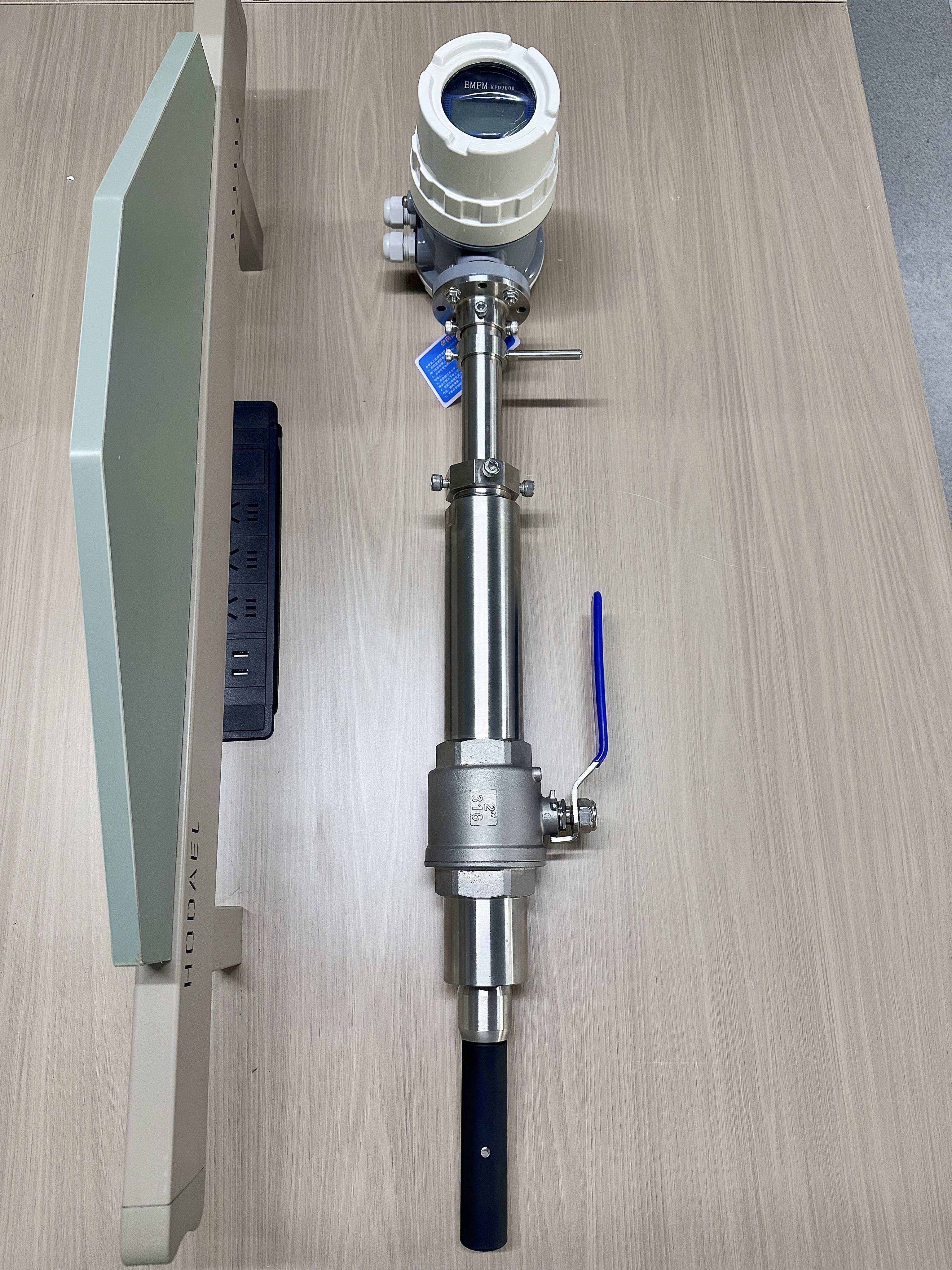
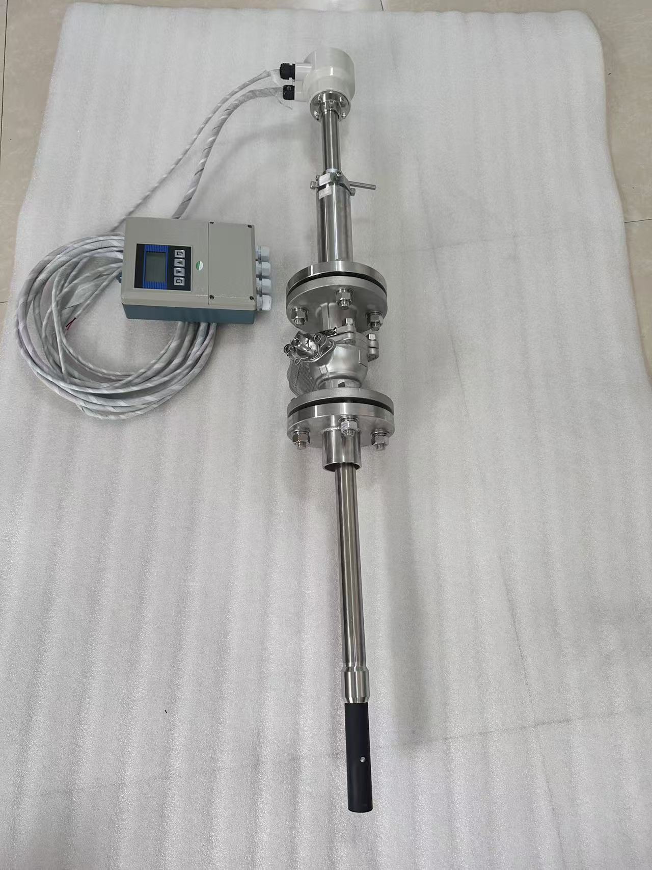
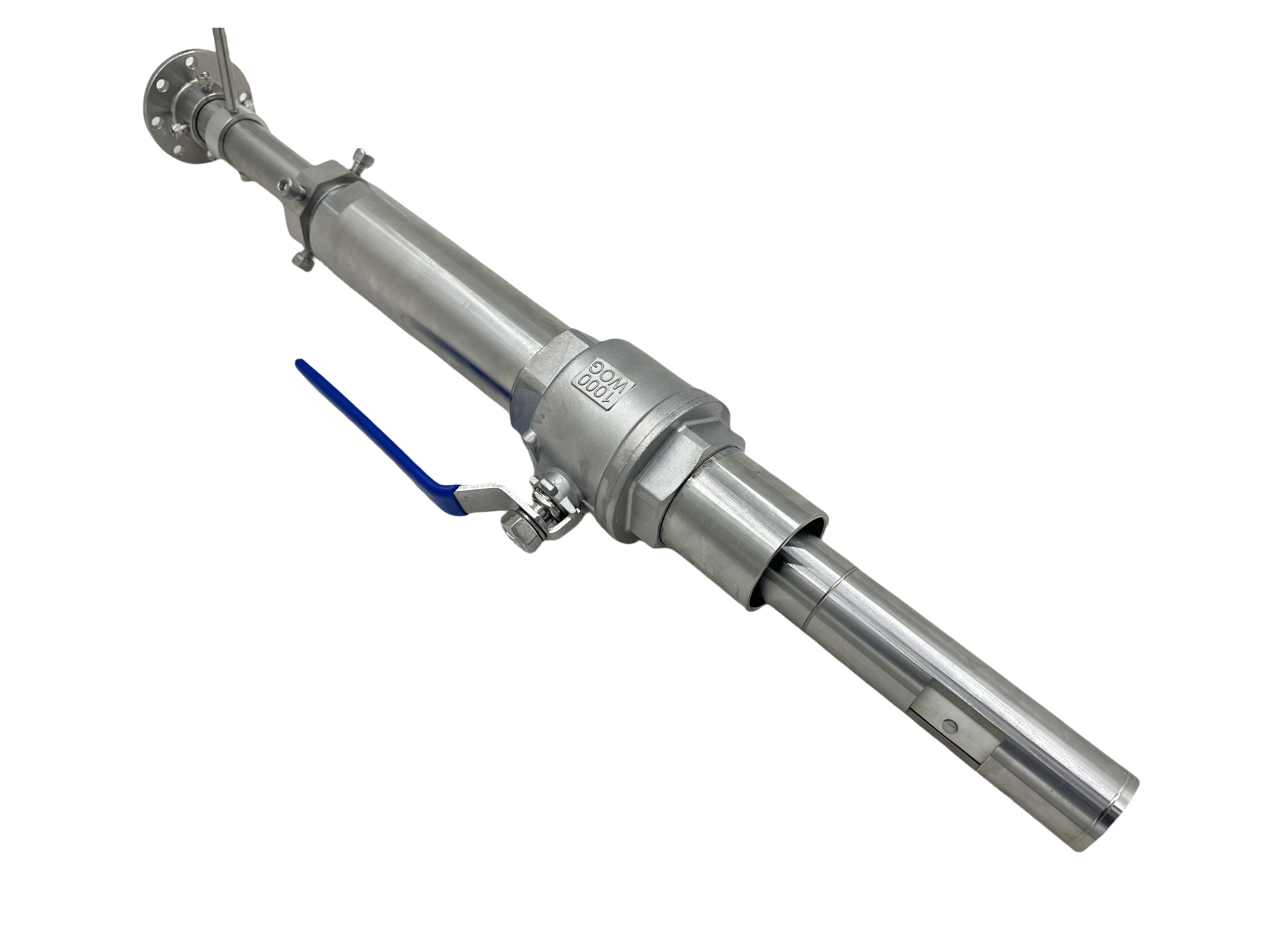
- Core structural components:
- Insert rod/sensor probe: It contains an excitation coil and a pair of measurement electrodes, serving as the core component inserted into the pipeline. Typically made from corrosion-resistant materials such as 316L stainless steel or Hastelloy alloys, the electrode surfaces can be coated with platinum or tungsten carbide to enhance performance.
- Sealed locking mechanism: Ensure reliable sealing and securement of the sensor in pressurized pipelines, typically achieved using ball valves or specialized clamps. Hot-swappable (No need to shut off the flow during installation/removal.)
- Converter (Transmitter): Responsible for generating excitation current, receiving weak electrode signals, performing signal amplification, filtering, computation, and outputting (such as 4-20mA, pulse, HART, Modbus, etc.).
II. Significant Advantages and Applicable Scenarios
- Core Advantages:
- Easy to install, low cost: The most distinctive feature is No need to cut off the pipeline or shut down the process. , it can be installed simply by drilling and welding the base, making it especially suitable for large-diameter pipelines of DN200 and above. Additionally, the equipment and installation costs are significantly lower compared to full-pipe electromagnetic flowmeters.
- Easy maintenance: Supports hot-swapping, allowing maintenance, cleaning, or sensor replacement without disrupting production.
- Minimal pressure loss: The sensor offers minimal resistance to the flow field, resulting in virtually no additional pressure loss and delivering excellent energy-saving performance.
- Wide range of applications: Measurable for various conductive liquids such as water, wastewater, acidic and alkaline solutions, mud, pulp, and more (conductivity ≥ 5 μS/cm).
- Typical application scenarios:
| Industry | Specific applications |
|---|---|
| Municipal Water Services | Monitoring of inlet and outlet main pipelines at the water treatment plant, zone-based metering of the distribution network, inflow/outflow flow rates at the wastewater treatment plant, and return sludge volume. |
| Industrial processes | Large-scale factory cooling water circulation systems, raw water/wastewater discharge metering, and large-diameter process water/solution flow monitoring in chemical processes. |
| Energy and Electricity | Measurement of circulating cooling water flow in power plants, raw water supply, and demineralized water flow. |
| Water Conservancy and Irrigation | Main canal and pump station effluent flow measurement. |
III. Key Installation Requirements and Precautions
Installation quality directly affects measurement accuracy and stability:
- Installation Location Selection:
- Straight pipe section requirements: Upstream ≥10D (pipe inner diameter), downstream ≥5D. Avoid flow disturbances caused by pumps, valves, bends, and other such sources.
- Flow direction: Ensure the sensor arrow points in the same direction as the fluid flow.
- Pipe fullness: It must be ensured that the measurement point is located at Full pipe Status: Avoid installing at the highest point of the pipe or in locations where gas may accumulate.
- Insertion depth and direction:
- The sensor insertion depth must be precise (typically inserted to the pipe's central axis or a specified depth point), as different manufacturers may have specific requirements.
- Common insertion directions: For horizontal pipes, prefer inserting at a ±45° angle (to prevent electrode deposition of solids or bubble accumulation at the top); for vertical pipes, insertion can be done from bottom to top.
- Grounding and Shielding:
- The pipeline must be properly grounded (especially non-metallic pipelines require the installation of a grounding ring or grounding electrode) to eliminate common-mode interference.
- Signal cables must use shielded cables, with the shielding layer reliably grounded at one end (typically at the converter end).
- Inserting the opening and sealing:
- Use a dedicated hole-opening tool to ensure the hole is smooth and free of burrs.
- Sealed locking devices (such as ball valves) must be pressure-resistant and leak-free.
IV. Limitations and Mitigation Strategies
- Relatively low precision: Typically, the accuracy is ±1–2% of the rate, which is lower than that of full-pipe high-precision electromagnetic flowmeters (±0.2–0.5%). It is well-suited for large-flow monitoring applications where precision requirements are not overly stringent.
- Sensitive to flow velocity distribution: The measurement is of local point velocity, which must be multiplied by the velocity distribution coefficient (K-factor) to calculate the average flow velocity. The installation location must meet the requirements for straight pipe sections to ensure a stable flow field, and the K-factor needs to be accurately calibrated.
- Not applicable for small pipe diameters: When the pipe diameter is too small (typically < DN150), the insertion rod causes greater disturbance to the flow field, leading to reduced accuracy and poor economic performance.
- Electrodes are highly susceptible to contamination/fouling: In systems prone to scaling or containing viscous media, the electrodes require regular maintenance and cleaning.
V. Key Points for Maintenance and Care
- Regular check-ups: Check the sensor insertion rod for sealing integrity, cable connections, and the converter's operational status.
- Electrode Cleaning: Clean the electrodes regularly—online or offline, such as every 3 to 6 months—to remove dirt and deposits. Methods include using a mechanical soft brush, ultrasonic cleaning, or chemical soaking (ensure compatibility with the materials).
- Zero-point calibration: Perform zero-point calibration in a fully filled pipeline with no flow to eliminate drift.
- K-factor verification: When a major overhaul is performed or if there are doubts about accuracy, the K-factor can be verified using the comparison method (such as with a portable ultrasonic flowmeter) or the volumetric method.
6. Trends in Intelligent Development
- Self-Diagnosis and Predictive Maintenance: Integrated sensor condition monitoring (such as electrode contamination levels and coil status) uploads diagnostic information via protocols like HART, Profibus PA, and Modbus, enabling predictive maintenance.
- Wireless Transmission Integrated with the Internet of Things: Supports battery-powered wireless transmission modules (such as LoRaWAN, NB-IoT), enabling convenient remote pipeline monitoring.
- Multi-parameter measurement: Some high-end models can simultaneously measure temperature and calculate heat.
- New Materials and New Processes: Adopt more wear- and corrosion-resistant electrode/liner materials (such as tungsten carbide, PFA) to enhance long-term stability.
Conclusion: The insertion-type electromagnetic flowmeter, with its core advantages of convenient installation, high cost-effectiveness, and easy maintenance, has become the ideal solution for monitoring the flow of conductive liquids in large-diameter pipelines. A thorough understanding of its operating principles, strict adherence to installation guidelines, and careful selection and maintenance tailored to the specific characteristics of the medium are essential for ensuring its long-term, stable, and reliable performance. As intelligent, wireless, and advanced material technologies continue to integrate into this field, insertion-type electromagnetic flowmeters will unlock even greater value in areas such as smart water management and industrial IoT applications.
Keywords: Analysis and Application Practices of Insertion Electromagnetic Flowmeters
Related information
Company News
-
Zhongce Sensing Slurry-Type Electromagnetic Flowmeter: Precision Measurement of Harsh Slurries Through Craftsmanship-Driven Materials and High-Frequency Excitation Technology
Release time:2026-04-15
-
Factors to consider when purchasing an intelligent electromagnetic flowmeter
Release time:2025-01-03
-
What type of flow meter is best for measuring flow rate in the petroleum industry?
Release time:2025-05-08
-
Factors to consider when purchasing a smart electromagnetic flow meter
Release time:2025-04-08
-
What type of flow meter is best suited for measuring flow rate in the petroleum industry?
Release time:2025-04-08
-
The explosion-proof performance of various instruments is extremely important in the chemical production process!
Release time:2025-04-08
Industry News
-
Henan Zhongce Sensor Scraper-Type Electromagnetic Flowmeter: A High-Reliability Flow Measurement Solution for Applications Prone to Scaling
Release time:2026-04-28
-
Product Selection Guide for Zhongce Sensing Insertion Electromagnetic Flow Meters: CLD-6034 and CLD-8028 Series
Release time:2026-04-10
-
Zhongce Sensing Slurry-Type Electromagnetic Flowmeter: a wear-resistant solution specifically designed for measuring mud, mineral slurry, and pulp.
Release time:2026-03-12
-
Henan Zhongce Sensor Miniature Electromagnetic Flowmeter: Designed for Precise Measurement of Small Flow Rates
Release time:2026-03-05
-
Zhongce Sensing Electromagnetic Water Meter: Precise Measurement, Empowering Smart Water Management
Release time:2026-01-27
-
Zhongce Sensing Scraper-Electrode Electromagnetic Flowmeter: A Reliable Measurement Solution for Adhesive Media
Release time:2026-01-10
-
High-Pressure Electromagnetic Flow Meters: Customized Solutions for Tough Industrial Challenges
Release time:2025-12-26
-
Zhongce Sensing Miniature Electromagnetic Flowmeter: Precise Measurement, Wide Range of Applications
Release time:2025-12-11
-
Precision Measurement, Outstanding Performance: A Comprehensive Analysis of Zhongce Sensing’s Insertion Electromagnetic Flowmeter
Release time:2025-12-08
-
Zhongce Sensing Filling Electromagnetic Flowmeter: The Domestic, Precision Choice for the Food and Beverage Industry
Release time:2025-11-22
-
Henan Zhongce Sensing Electromagnetic Flowmeter: Precise Measurement, Monitoring Industrial Processes
Release time:2025-11-18
-
Zhongce Sensing Filling Electromagnetic Flowmeter: The Perfect Combination of PFA Lining and Class 0.5 Accuracy
Release time:2025-11-04
-
Miniature Electromagnetic Flow Meters: Industrial Powerhouses for Precisely Measuring Tiny Flow Rates
Release time:2025-10-30
-
Zhongce Sensing High-Pressure Electromagnetic Flowmeter: Professional Measurement, Customized Solutions
Release time:2025-10-23
-
Specifically Designed for Ultra-Low Flow Measurement: Technical Analysis and Application Guide for Zhongce Sensing’s DN6 Electromagnetic Flowmeter
Release time:2025-10-14
-
Precise Measurement, Smart Choice: A Comprehensive Analysis of Zhongce Sensing's Pipeline-Type Intelligent Electromagnetic Flowmeter
Release time:2025-09-23
-
Zhongce Sensing Filling Electromagnetic Flowmeter: The Core Tool for Precise Measurement
Release time:2025-09-20
-
Analysis and Application Practices of Insertion Electromagnetic Flowmeters
Release time:2025-09-17
-
Technical Analysis of Slurry-Type Electromagnetic Flowmeters
Release time:2025-09-17
-
Precision measurement, replacing imports: Newly launched filling electromagnetic flowmeters empower the beverage and pharmaceutical industries.
Release time:2025-09-12
-
Zhongce Sensing Insertion Electromagnetic Flowmeter: Parameter, Installation, and Selection Guide
Release time:2025-08-05
-
Zhongce Sensing Electromagnetic Water Meter: The Pioneer of Precise Measurement in the Era of Smart Water Management
Release time:2025-08-05
-
Zhongce Sensing Pipeline Electromagnetic Flowmeter: Precise Measurement, the Reliable Choice for Fluid Flow Applications
Release time:2025-07-29
-
Micro and Miniature Electromagnetic Flow Meters: Small Size, Big Impact—Precision Measurement Empowers High-Precision Industries
Release time:2025-07-24
-
Zhongce Sensing's Miniature Electromagnetic Flowmeter: A Highly Efficient and Precise Choice for Measuring Small Flows
Release time:2025-07-19
-
Zhongce Sensing Insertion Electromagnetic Flowmeter: A Highly Efficient and Convenient Solution for Fluid Measurement
Release time:2025-07-19
-
Henan Zhongce Sensor Electromagnetic Water Meter | IP68 Waterproof + Wireless Remote Transmission—Your First Choice for Smart Water Management and Precise Measurement
Release time:2025-07-16
-
Henan Zhongce Sensor Pipeline Electromagnetic Flowmeter: The Industrial Choice for High-Precision Fluid Measurement
Release time:2025-07-16
-
Micro and Miniature Electromagnetic Flow Meters: The Ideal Tool for Precisely Measuring Tiny Flow Rates
Release time:2025-07-14
-
What are the maintenance methods for electromagnetic flow meters?
Release time:2025-05-08
-
Difference between electromagnetic water meters and electromagnetic flow meters
Release time:2025-05-08
-
Advantages of electromagnetic flow meters
Release time:2025-05-08
-
Internal structure of a magnetic flow meter
Release time:2025-05-08
-
Electromagnetic flow meter principle
Release time:2025-05-08
-
Troubleshooting common malfunctions of electromagnetic flow meters
Release time:2025-05-08
You may also want to consult
Leave the information you want to consult, and we will contact you as soon as possible

Address: No. 181, Changxing Road, Changxing Road Street, Changge City, Xuchang City, Henan Province

二维码
Copyright © Henan Zhongce Sensor Manufacturing Co., Ltd. www.300.cn SEO Privacy Policy